 I crack open box of my electronics stuff and start taking inventory. My plan is to use the chips I have to drive 7-segment displays to drive a home-built over sized 7-segment display. Think old school game shows before everything became LCD screens.
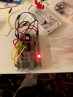
I start with a breadboard, add a 7-segment display and a CD4511 7-segment display driver chip, and wire it to a USB battery. Great success as I can display all the numbers I need by changing around the jumper wires.
Next step I hookup an Arduino and control the inputs that way. It looks like I have my successful proof-of-concept.
The first real problem I encounter is how do I build the clock circuitry and it looks like that's going to harder than the display component. Things change as I find out the ESP32 can be used with Arduino IDE and I can have the ESP32 call out to an NTP time server and set its own internal clock.
Now I have the clock and the display drivers all that remains is building the numbers and figuring how how to power thing without burning out my logic chips.
I start my research into different ways to drive large, bright LED displays and I come across NeoPixels RGB strips.They can cut with scissors and soldered in a chain easily. I do the math on how many LED's I need and I order a 100-LED strip from Amazon.
I get the strand in the mail and right away start playing with it by hooking up power and data lines. Nothing happens. This is real bummer, I take out my multi-meter, check power levels, check the connections, everything seems fine. After a while of confusion and frustration I come up with the idea to plug wires into the other end of the strip and everything lights up. I run sample program and it's magical, I ever think I hear music playing (probably just in my head). This will work.
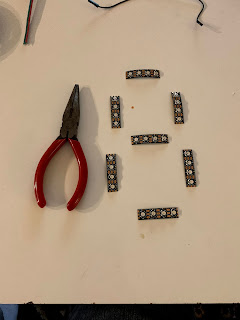
Actual construction begins and the first thing I need is a box to mount the digits in. After some searching and head scratching I decide the perfect box will be the tray from a case of water bottles so I run out to Target late that night to pick up some paint brushes and black paint. After the paint dries, I cut out paper outlines to size display, mark rectangles with pencil and then start cutting the LED strip into 4 light segments; no turning back now.
Laid out the first digit, cut the lengths of wire, soldered one segment to the next until the whole first 7-segment display built. The moment of truth comes as I mount it in the box, tape it down with electrical tape and plug it in.
And it kind of works. Re-solder some flaky joints and I have myself a device that display any number between 0 and 9. Thirty-two careful wire solders later (not counting re-solders) and I have myself a working clock display.

|

|
I finished up by moving the ESP32 and the LED power supply to the right size breadboard and mounting it to the back of the box. Wrote the code in the Arduino IDE and put it on GitHub (https://github.com/tachyonknave/NeoClock_ESP32). Final step was testing it from the swimming pool and it was perfect.
Future plans: Add a flashing dots between hour and minute. Set up a web server to control it over WiFi that will allow additional functions such as 20 second countdown for heartbeat, show the date periodically, timer mode to count up or count down, change the colors and switch between 12 and 24 hour mode.


